
How to Create a Use Case Diagram
A use case diagram is one of those UML diagrams that looks simple at first glance, yet it carries a surprising amount of meaning when it is done well. It is often the first diagram teams draw when they want to understand a system from the user’s point of view, because it helps answer a fundamental question: who uses the system, and what do they need to achieve with it? That question may sound basic, but in real projects it becomes the anchor for gathering requirements, aligning stakeholders, and preventing the kind of confusion that leads to expensive redesigns later. A use case diagram does not try to show every technical detail. It does not tell you how a database is structured, how APIs communicate, or how classes are implemented. Instead, it gives you a clear, high-level picture of interactions between users and a system. That is exactly why it remains so useful, even in modern agile teams where software evolves quickly. When people talk about clarity in software design, they often mean the ability to see the product from the outside in, and that is where a use case diagram shines.
Before drawing anything, it is worth understanding the mindset behind the diagram. Many beginners treat it like a decorative sketch, a box with stick figures and ovals connected by lines. In practice, it is far more valuable than that. A good use case diagram forces you to think carefully about boundaries, roles, goals, and shared responsibilities. It encourages you to separate the system from the people and external services around it. It also helps expose gaps in requirements. For example, if you are modeling an online store and you have an actor called “Customer,” it becomes natural to ask what the customer can actually do: browse products, add items to cart, apply coupons, place an order, track a shipment, and request a refund. Suddenly, the conversation moves from vague ideas to concrete behavior. That shift matters. It is often the difference between “we think users can do this” and “we have explicitly agreed that this is what the system supports.”
A use case diagram is also one of the easiest UML diagrams to communicate to non-technical stakeholders. Business analysts, product owners, QA testers, and even clients who have never seen a class diagram can usually understand it after a short explanation. That makes it a great bridge between business needs and technical planning. It is not the final word on system design, but it is an excellent starting point. When you create it thoughtfully, it becomes a shared reference that teams can return to throughout development. It can even help during testing, because each use case can inspire test scenarios, acceptance criteria, and user stories. In that sense, the diagram is not just a visual artifact. It is a thinking tool.
What a Use Case Diagram Really Shows
At its core, a use case diagram shows the relationship between external actors and the ways they interact with a system. An actor is anything outside the system that participates in a use case. That is usually a person, such as a customer, admin, or employee, but it can also be another system, a device, or an external service. A use case is a goal-oriented action that the system offers to one or more actors. The use case should describe what the system does from the user’s perspective, not how it is internally implemented. That distinction is important because beginners often mix up use cases with internal tasks. “Validate payment” might be part of the system’s process, but “Place order” is more likely the use case because it represents a user goal.
The use case diagram also includes a system boundary, which is a rectangular box surrounding the use cases that belong to the system. Everything inside the box is part of the system under analysis. Everything outside the box is an actor or external dependency. This boundary matters because it keeps the model focused. It tells the viewer what the system is responsible for and what it is not responsible for. If a shopping platform integrates with a payment gateway, for example, the payment gateway should appear outside the boundary, because it is external to the system being modeled. That simple visual separation often reveals architectural responsibility in a clean and memorable way.
The diagram can also express relationships between use cases, most commonly include, extend, and generalization. These relationships help show reuse, optional behavior, and specialization. They are powerful, but they should be used carefully. Too many relationship arrows can make a use case diagram harder to read than a simple set of use cases with clear labels. The best diagrams are not the ones packed with notation; they are the ones that communicate a system’s purpose without forcing the viewer to decode unnecessary complexity. In other words, clarity is more important than decoration.
Why Use Case Diagrams Matter in Real Projects
In a real project, requirements are rarely handed to you in a neat, complete document. More often, they arrive as meeting notes, half-formed ideas, feature requests, user complaints, and assumptions that different stakeholders believe are obvious. A use case diagram helps organize that chaos. It gives the team a common visual language. Instead of debating abstract statements like “the system should be easy to use,” you can discuss specific goals such as “a guest user can search products” or “an admin can deactivate an account.” That level of specificity makes requirements easier to validate, estimate, and test.
These diagrams are also useful because they support incremental discovery. You might begin with a rough model and then refine it as you learn more. At first, you may identify only the primary actors and top-level use cases. Later, you may break some use cases into smaller pieces, add relationships, or clarify boundary conditions. That flexibility makes the diagram suitable for both early discovery and ongoing refinement. It is not frozen in time. It grows with the understanding of the system.
Another reason they matter is that they help teams avoid implementation bias too early. Engineers naturally think in terms of services, classes, modules, endpoints, and state transitions. That is valuable, but requirements work needs a different lens first. A use case diagram delays technical bias and keeps the focus on user goals. This helps teams avoid designing a system around internals before they understand the actual needs of the people who will use it. A healthy design process usually starts with behavior and only later descends into structure. The use case diagram is one of the best tools for that first stage.
Step 1: Define the System You Are Modeling
The first step is to be very clear about what system you are actually drawing. This sounds obvious, but it is one of the most common places where people get confused. Are you modeling a whole company platform, a mobile app, a payment service, a checkout module, or a library management system? The answer changes everything. A use case diagram needs a defined scope. If the scope is too broad, the diagram becomes overloaded and difficult to read. If the scope is too narrow, it may miss the larger user experience. You need a scope that is meaningful but manageable.
A good way to define scope is to state the system in one sentence. For example, “The system is an online food delivery application.” From that sentence, you can already infer that customers, restaurant managers, delivery drivers, and admins may be actors. You can also infer likely goals such as registering, ordering food, tracking delivery, and managing menus. The system statement becomes the center of the model. Without it, the diagram may drift into unrelated functions that belong to other systems.
This is also the point where you should decide what is inside the system boundary and what is outside. Suppose you are modeling a hospital appointment system. The hospital staff may be actors, but the SMS gateway used to send notifications is probably an external system. The payment processor may also be external. These decisions help keep the diagram honest. They also force you to think about integrations. A use case diagram does not need to show every protocol, but it should reveal the major external dependencies that matter to user interactions.
Step 2: Identify the Actors
Once the system is defined, the next step is to identify the actors. Actors represent the roles that interact with the system. Notice that the word “roles” is more useful than “people,” because one person may play multiple roles. For example, in a learning platform, the same individual might be both a student and an instructor. In a banking system, the same customer might be a regular user, an account holder, and in some cases an administrator. Thinking in terms of roles prevents you from oversimplifying the model.
To identify actors, ask who or what interacts with the system from outside. Start with the obvious ones, then look for external systems and specialized roles. For an e-commerce system, the obvious actors might be Customer, Admin, and Payment Gateway. For a school management system, actors might include Student, Teacher, Registrar, and Notification Service. For a healthcare booking platform, possible actors might be Patient, Receptionist, Doctor, and Insurance System. The exact set depends on the scope.
A common mistake is to create too many actors too early. Sometimes teams list every possible user type, even when those roles do not truly change the system’s behavior. If two roles perform the same actions in the system, they may not need separate actors. Conversely, if one role has a unique responsibility that changes the set of available use cases, it probably deserves its own actor. The art is in choosing a meaningful level of abstraction. You want just enough detail to represent real differences in interaction, but not so much that the diagram becomes cluttered.
Step 3: Discover the Use Cases
After identifying the actors, list the things they want to achieve using the system. These are the use cases. This step is usually easier if you phrase each use case as a goal rather than a function. For example, “Register an account,” “Log in,” “Browse products,” “Place an order,” and “Request a refund” are goal-oriented. “Validate email format,” “Generate order ID,” or “Store password hash” are implementation details and belong elsewhere. The use case should describe an outcome a user cares about.
A practical way to discover use cases is to interview stakeholders or imagine user journeys. Ask what each actor wants to do. For a customer in an online store, the goals may be to search products, view details, add items to a cart, check out, and track an order. For an admin, the goals may be to manage users, update inventory, approve refunds, and view reports. For an external payment gateway, the use case may be something like “Process payment,” though in a strict modeling sense the gateway is usually an actor participating in the payment-related use case rather than owning the use case itself.
Not every action deserves its own use case. A use case should represent a meaningful interaction, not a microscopic step. If the step is a sub-action that always happens as part of another use case, it may be better modeled as part of that larger use case, or as an include relationship if you need to highlight reuse. For example, “Authenticate user” may be included by both “Place order” and “View account details.” That is useful if authentication is a shared prerequisite you want to make explicit. But if every detail is turned into a separate use case, the diagram loses its elegance and becomes a catalog of chores.
Step 4: Draw the System Boundary
Now that you have actors and use cases, place the system boundary around the use cases that belong to your system. This is usually a rectangle labeled with the system name. The actors remain outside the rectangle. The use cases are inside it. This simple shape carries an important message: the diagram is about the system and the interactions around it, not about the whole world.
The boundary can help settle debates about responsibility. For instance, in a hotel booking system, should “Send confirmation email” be inside the boundary? That depends on whether the system itself sends the email or whether it hands the task off to an external service. If the system internally manages notifications, the use case may be inside. If email sending is fully external and invisible to the system’s behavior, it may be modeled differently. The point is not to force a universal answer, but to make responsibility visible and discussable.
The boundary also helps with consistency. When a diagram has no clear boundary, actors and use cases can blend together visually. The result is confusing. The viewer cannot tell which elements are part of the system and which are outside. By drawing the boundary early, you create a clean structure that makes the rest of the diagram easier to understand. It is a small step with a big payoff.
Step 5: Connect Actors to Use Cases
Once the boundary is in place, connect each actor to the use cases they participate in. In a use case diagram, a solid line usually represents an association between an actor and a use case. The line simply indicates interaction. It does not mean ownership, data flow, or order of execution. That is another common misunderstanding. A line between a customer and “Place order” means the customer participates in that use case, not that the customer controls every internal detail of the process.
When drawing these connections, think carefully about who actually uses the function. A “Guest” may be able to browse products but not place an order. An “Admin” may manage products but not necessarily buy them. A “Registered User” may be able to access profile settings, while a “Support Agent” may only be able to view customer tickets. These relationships express business rules in a visual way.
It is also worth checking for shared use cases across multiple actors. For example, both a Customer and an Admin might log in. In that case, the login use case may be connected to both actors. This can reveal reusable behavior that should be documented once and then referenced in multiple places. Shared interactions are one of the strengths of use case modeling because they make common behavior visible without duplication.
Step 6: Use include When a Use Case Always Reuses Another One
The include relationship is used when one use case always invokes another as part of its behavior. It is a way of factoring out common behavior. Suppose you have “Place order” and “Checkout,” and both require “Authenticate user.” If authentication is a mandatory part of both flows, you may model it as an included use case. This shows that the reused behavior is not optional; it is always part of the parent use case.
include is helpful when a function is reused across multiple use cases and you want to avoid repeating it conceptually. However, it should not be overused. Not every repeated idea needs a separate included use case. Sometimes a short note in the use case description is enough. The diagram is a communication tool, not a replacement for all textual requirements.
Here is a small PlantUML example that demonstrates a simple include relationship:
@startuml
left to right direction

actor Customer

rectangle "Online Store" {
  usecase "Place Order" as UC1
  usecase "Authenticate User" as UC2
  usecase "Checkout" as UC3
}

Customer --> UC1
UC1 ..> UC2 : <<include>>
UC1 ..> UC3 : <<include>>
@enduml
In this example, the customer participates in “Place Order,” and that use case includes “Authenticate User” and “Checkout.” This is a concise way to show that those sub-behaviors are essential parts of the main process. It is especially useful in larger systems where many use cases share common steps.
Step 7: Use extend for Optional or Conditional Behavior
The extend relationship is used for behavior that happens only under certain conditions or as an optional variation of a base use case. This is different from include, where the behavior is always part of the flow. Imagine a use case called “Apply discount.” It might extend “Checkout” because a discount is only applied if the customer enters a valid coupon or qualifies for a promotion. Likewise, “Send fraud alert” might extend “Process payment” if suspicious activity is detected.
This relationship is useful because it lets you keep the base use case simple while still showing exceptional or optional behavior. It is a way to model branches and variations without cluttering the main interaction. That said, extend can be confusing if used carelessly. People often misuse it when they really mean “sometimes this happens.” The key question is whether the extension is truly optional and condition-based. If it is always needed, use include instead. If it is a rare exception or optional enhancement, extend may be the right choice.
Here is a Mermaid example showing extend:
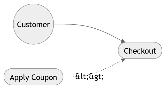
This example expresses that applying a coupon is an extension of checkout. The exact notation can vary by tool, but the concept remains the same: the optional behavior hangs off the base use case rather than replacing it.
Step 8: Consider Generalization When Actors or Use Cases Share a Common Shape
Generalization is another relationship that can be useful in use case modeling. It shows inheritance or specialization. For actors, this means one actor is a specialized kind of another. For example, “Premium Customer” may be a specialization of “Customer.” A premium customer can do everything a customer can do, plus extra things like access exclusive offers. Likewise, “Manager” may be a specialization of “Employee” if the manager has all employee capabilities plus additional privileges.
The same idea applies to use cases. You might have a general use case such as “Manage account,” with specialized forms like “Update profile,” “Change password,” and “Delete account.” This is useful when the specialized use cases share common structure but differ in details. Generalization can reduce repetition and help reveal a clean hierarchy. Still, like every UML relationship, it should be used because it clarifies the model, not because it sounds sophisticated. Simplicity wins when the diagram is meant for communication.
Step 9: Keep the Diagram at the Right Level of Detail
One of the biggest mistakes people make is overloading the use case diagram with too much detail. A use case diagram is not a workflow diagram. It is not a sequence diagram. It does not need every click, screen, or backend action. Its job is to give an overview of system behavior. If you try to show every branch and exception directly in the diagram, it becomes hard to read and loses its purpose.
The right level of detail is usually the level where a stakeholder can understand the system’s major functions in a minute or two. If the diagram takes a long explanation just to interpret, it is probably too detailed. If it is so abstract that no one can tell what the system does, it may be too shallow. A good use case diagram often contains a handful of actors and a focused set of use cases. For a large system, it is often better to create multiple diagrams by feature area than one giant diagram full of tangled lines.
This is where judgment matters. Sometimes a project team wants a single diagram for the whole platform, but that can quickly become unreadable. A better approach is to create one overview diagram and then separate diagrams for modules like authentication, billing, reporting, or administration. That makes the model easier to maintain and much easier to discuss with different stakeholders.
Step 10: Write Clear Use Case Names
The naming of use cases matters more than many people realize. Good names make the diagram readable. Poor names make it feel vague or technical. Use cases should usually begin with a verb and describe a user goal. Examples include “Register Account,” “Search Products,” “Submit Ticket,” “Generate Report,” and “Track Delivery.” These names are clear and action-oriented.
Avoid names that sound like internal code structures or vague nouns. “User Management,” “Order Processing,” and “System Maintenance” may be too broad unless they truly represent a meaningful user goal at the scope you are modeling. In many cases, such phrases hide several actual use cases. For example, “User Management” may need to be broken into “Create User,” “Deactivate User,” “Assign Role,” and “Reset Password.” That kind of decomposition makes the model much more useful.
The same principle applies to actor names. Use role-based names rather than individual names. “Customer,” “Admin,” “Teacher,” “Student,” “Doctor,” and “Supplier” are more useful than “John” or “Sara.” The diagram is about roles, not specific people.
Step 11: Validate the Diagram with Stakeholders
Once you have a draft, share it with the people who understand the domain. This may include business owners, product managers, developers, testers, and end users. Ask whether the actors are correct. Ask whether any major goal is missing. Ask whether any use case is mislabeled or too technical. Ask whether the system boundary feels accurate. This review step is where the diagram becomes truly valuable, because it surfaces misunderstandings before they become costly.
A useful validation question is this: “Does this diagram reflect what users expect the system to help them do?” That question keeps the discussion grounded in value rather than mechanics. Another useful question is: “Are we modeling the right level of detail?” Sometimes the answer is that a use case should be split. Other times, it should be merged. The review process is not about proving the first draft was perfect. It is about discovering the right model together.
Stakeholder validation is especially important because use case diagrams often look straightforward even when they hide assumptions. Two people may look at the same diagram and mentally fill in missing behavior differently. Reviewing the diagram openly can expose those differences early. That is one of the strongest reasons to create it in the first place.
A Full Example: Online Food Delivery System
Let us walk through a practical example from start to finish. Suppose the system is an online food delivery platform. The main goal is to allow customers to browse restaurants, order meals, and track delivery. Restaurants need to manage their menus. Delivery drivers need to view assigned orders and update delivery status. Admins need to oversee the platform. External services may include payment processing and notifications.
The actors might be:
Customer
Restaurant Owner
Delivery Driver
Admin
Payment Gateway
Notification Service
The use cases might include:
Browse Restaurants
View Menu
Add to Cart
Place Order
Make Payment
Track Delivery
Cancel Order
Manage Menu
Accept Order
Update Delivery Status
Manage Users
Send Notification
A diagram for this system could show the Customer interacting with browsing, ordering, paying, and tracking. The Restaurant Owner could interact with managing the menu and accepting orders. The Delivery Driver could update delivery status. The Admin could manage users and monitor platform activity. The Payment Gateway and Notification Service could be external actors involved in payment and messaging related use cases.
Here is a PlantUML sketch:
@startuml
left to right direction

actor Customer
actor "Restaurant Owner" as RestaurantOwner
actor "Delivery Driver" as Driver
actor Admin
actor "Payment Gateway" as PG
actor "Notification Service" as NS

rectangle "Food Delivery System" {
  usecase "Browse Restaurants" as UC1
  usecase "View Menu" as UC2
  usecase "Add to Cart" as UC3
  usecase "Place Order" as UC4
  usecase "Make Payment" as UC5
  usecase "Track Delivery" as UC6
  usecase "Cancel Order" as UC7
  usecase "Manage Menu" as UC8
  usecase "Accept Order" as UC9
  usecase "Update Delivery Status" as UC10
  usecase "Manage Users" as UC11
  usecase "Send Notification" as UC12
}

Customer --> UC1
Customer --> UC2
Customer --> UC3
Customer --> UC4
Customer --> UC5
Customer --> UC6
Customer --> UC7

RestaurantOwner --> UC8
RestaurantOwner --> UC9

Driver --> UC10
Admin --> UC11

PG --> UC5
NS --> UC12

UC4 ..> UC5 : <<include>>
UC4 ..> UC12 : <<include>>
UC7 ..> UC12 : <<include>>
UC10 ..> UC12 : <<include>>
@enduml
This example is not meant to be the only correct version. It is simply a demonstration of how a use case diagram starts to reflect real business interactions once you identify the main actors and goals. Notice how the diagram makes dependencies visible. Payment and notifications are not treated as afterthoughts. They are part of the user journey and the business process, so they deserve representation.
Another Example: Library Management System
A library system is a classic use case diagram example because it has clear roles and easy-to-understand goals. A Student may search the catalog, borrow books, reserve books, and return books. A Librarian may add books, remove books, issue loans, and manage fines. An external notification service may send due-date reminders.
The structure might look like this:
@startuml
left to right direction

actor Student
actor Librarian
actor "Notification Service" as NS

rectangle "Library Management System" {
  usecase "Search Catalog" as UC1
  usecase "Borrow Book" as UC2
  usecase "Reserve Book" as UC3
  usecase "Return Book" as UC4
  usecase "Manage Inventory" as UC5
  usecase "Issue Loan" as UC6
  usecase "Manage Fines" as UC7
  usecase "Send Due Reminder" as UC8
}

Student --> UC1
Student --> UC2
Student --> UC3
Student --> UC4

Librarian --> UC5
Librarian --> UC6
Librarian --> UC7

NS --> UC8
UC2 ..> UC8 : <<include>>
UC4 ..> UC8 : <<include>>
@enduml
Again, the diagram highlights user goals and shared behavior. It keeps the model readable while showing enough detail to be genuinely useful.
Common Mistakes to Avoid
One frequent mistake is drawing too many internal technical details. Use case diagrams are not meant to show database tables, UI states, or service classes. Another mistake is naming use cases like system functions instead of user goals. “Update database” is not a use case. “Save profile changes” is much closer to the right level.
A second common mistake is failing to define the system boundary clearly. Without it, the diagram may feel like a random collection of icons. A third mistake is creating actors for anything that touches the system, even if that thing is not actually a role in the interaction model. A payment provider may be an actor if it participates in the use case, but a database usually is not.
Another issue is overusing include and extend. These relationships are valuable, but they should not be forced into every diagram. If they make the diagram harder to understand, consider whether the reuse can be described more simply in text. A use case diagram should clarify, not impress.
Finally, a common beginner mistake is mixing use case diagrams with activity diagrams. If you want to show a process step-by-step, use an activity diagram or a flowchart. If you want to show who can do what with the system, use a use case diagram. Each diagram has its own purpose. Knowing that difference helps you choose the right tool.
Best Practices for Creating Strong Use Case Diagrams
A strong use case diagram starts with the simplest meaningful version of the system. Begin broad, then refine. Use role-based actors. Use verb-based use case names. Keep the diagram focused on goals rather than mechanics. Use relationships only when they genuinely improve understanding. And above all, review it with people who understand the domain.
It also helps to separate high-level and detailed views. One diagram might present the entire system at a glance. Another may zoom into a specific module such as authentication or checkout. This layered approach makes the model easier to understand and maintain. It also allows different audiences to use the level of detail they need. Executives may only need the overview, while analysts may want the more detailed diagrams.
Another good practice is to keep textual notes alongside the diagram. A use case diagram is often strongest when paired with short descriptions for each use case. Those descriptions can include preconditions, postconditions, main flow, alternative flow, and business rules. The diagram gives the visual map, and the text gives the behavioral depth. Together they form a far more complete picture.
A Human Approach to Diagramming
It is easy to become mechanical when drawing UML. You start thinking in symbols instead of in people. That is when the diagram loses its value. The best use case diagrams begin with empathy. What does each user actually need? What outcome are they trying to achieve? What problem is the system solving for them? When you keep those questions in mind, the diagram becomes more natural and more truthful.
This human perspective also helps avoid overengineering. Not every project needs a highly detailed UML model. Sometimes a small, clean use case diagram is enough to align a team and start building. Sometimes it becomes the seed of a larger requirements document. Sometimes it is simply a shared sketch that keeps everyone honest about what the product is supposed to do. That is still valuable. Software projects often fail not because the code is weak, but because the understanding of the problem was weak. A use case diagram helps strengthen that understanding.
There is also something reassuring about seeing a system in this form. The actors remind you that software is for people and services that have goals. The use cases remind you that the system exists to help accomplish those goals. The boundary reminds you that a system has limits, responsibilities, and integrations. Taken together, those elements create a compact story about how the software fits into the world. That story is often what teams need before they can move confidently into design and implementation.
Step-by-Step Recap
Here is the practical flow you can follow every time:
Start by defining the system scope clearly. Identify the external actors that interact with it. List the goal-oriented use cases for each actor. Draw the system boundary around the use cases. Connect actors to the use cases they participate in. Use include for mandatory reused behavior, extend for optional or conditional behavior, and generalization when specialization is meaningful. Review the result with stakeholders. Then refine until the diagram is simple, accurate, and easy to understand.
This process works well because it follows the way people naturally think about software behavior. First, what is the system? Then, who interacts with it? Then, what do they want to do? Only after that do relationships and variations become useful. That sequence keeps the model grounded and prevents confusion.
Final Thoughts
Creating a use case diagram is not about learning a notation for its own sake. It is about making requirements visible, shared, and discussable. When done well, the diagram becomes a conversation starter, a planning tool, and a way to reduce ambiguity. It helps teams focus on user goals instead of implementation noise. It also gives non-technical stakeholders a way to participate meaningfully in system design.
The most effective use case diagrams are usually not the most complicated ones. They are the ones that feel obvious once you see them, because they capture the real shape of the problem. That is the mark of a good diagram: it makes a complex system easier to think about. If you keep the system boundary clear, name actors and use cases carefully, and avoid unnecessary detail, you will create diagrams that are not only technically correct but genuinely useful. And in software projects, usefulness is what matters most.